Peregrine is an ice-penetrating radar-equipped small UAS designed to be low-cost and field portable.
This is the multi-page printable view of this section. Click here to print.
Peregrine Payload
Details about the Peregrine Radar Payload
1 - Peregrine Radar Payload Box Assembly
Build instructions for the core of the radar payload
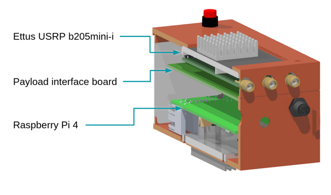
Major components of the Peregrine radar payload box
Bill of Materials
A complete bill of materials for the payload box is available in this Google Sheet, embedded below.
Some parts are custom made. See the Custom Parts page for suggestions on how to build these yourself or source them from reliable vendors. Design files for these parts are available in the Peregrine Hardware repository.
Assembly instructions
Preparing enclosure halves
The payload box is a clamshell-style design with two interlocking halves. The “upper” half contains the SDR. The “lower” half holds the Raspberry Pi. Sandwiched between the two halves is the “payload divider” PCB, which houses some sensors and provides for external connections.
Starting with the Pi Shell:
- Place 4x M2.5 heat inserts into the four mounting holes at the bottom of the box.
- Place 2x M2.5 heat inserts into the two front panel mounting holes on the front of the box.
Continuing with the SDR Shell:
- Place 4x M2.5 heat inserts into the four holes in the tabs sticking up, to accept bolts from the outside to connect the two shells together.
Copper foil wrapping
Why is the box wrapped in copper tape?
The SDR and the Pi communicate over a USB 3 interface. Unfortunately, USB 3 has known RF interference issues. The copper foil wrapping helps to minimize the impact of the noisy USB 3 connection on other devices. We have particularly had problems with GPS receivers (such as the one connected to the Peregrine autopilot) not being able to get a fix without this copper wrapping.
You can read more about the USB 3 interference issues from this Intel appnote.
Print out the cutout templates. The PDF contains cutout templates for the copper foil wrapping on the top and bottom of the enclosure.
Double check the dimensions
Use a ruler to measure the marked dimensions on the first page to make sure your print is at the right scale.Spread a layer of adhesive-backed copper out on a cutting-safe surface (such as a sacrificial piece of wood) and use some masking tape to hold it down. Tape the cutout template on top. Use an X-Acto knife (or similar) to cut:
- A small “X” across each of the external bolt holes (to allow a bolt to go through – no need to try to cut out the circle itself)
- The internal cutout for the heatsink
- The exterior outline of the entire piece.
If you’re not sure which lines to cut, take a moment to see how the paper folds around the 3D printed pieces. Your goal is to fully cover the exterior.
Carefully peel away the adhesive from part of the copper foil and start pasting it onto the 3D printed piece. It’s easier to do this bit by bit, rather than pulling the entire backing off at once.
Repeat with the other half of the enclosure.
2 - Data Storage Options
Options for how to store your radar data as its being recorded
There are three tested options for how to store your radar data, with various tradeoffs:
- MicroSD card – This is the default option that is assumed in the documentation.
- External USB SSD or Flash Drive
- NVMe SSD connected over PCIe interface (Pi 5 only)
MicroSD card
This is the easiest option since it’s built-in to the Raspberry Pi and requires no additional space or equipment.
MicroSD card quality varies significantly and counterfits are an issue. For this reason, purchasing from a reputable vendor is highly recommended.
We use Samsung Pro Plus MicroSDXC cards, usually in 512 GB capacity.
You can find lots of online benchmarks of various MicroSD cards, such as this one and this one.
There are two downsides to this approach:
- Above 1 TB, MicroSD cards start to get quite expensive.
- If you’re storing data on the MicroSD card, it’s not possible to use
overlayrootto protect the file system from corruption.
External USB drives
External USB 3 SSDs or flash drives may be plugged into the USB 3.0 ports on the Pi and used as storage devices. We have used Samsung T7 Shield SSDs successfully in field deployments. The major advantage of this approach is that it is easy to swap out storage devices.
NVMe SSD
Starting with the Pi 5, a PCIe port is exposed allowing for NVMe devices including SSDs to be added. We have succesfully used the Pimoroni NVMe Base.
This is the highest speed and most reliable storage option. The configuration we’ve tested so far has kept the OS and radar code on the MicroSD card and used the SSD only for storage. It is, however, possible to boot directly from an NVMe SSD, though this configuration has not been tested with ORCA.
3 - External button
An external lighted push button can be added to turn the radar on and off. A connector for this is included on the Payload Divider PCB.
Button choices
The intended button for the UAV version is HB15CKW01-5C-CB.
Most other similar buttons can be used. For the ground-based version, we use ULV4F2BSS311. Some of the photos on this page are taken with this button, which can be mounted externally.
Wiring the button
The button connector is a 5 position JST GH connector. The connectors and pre-crimped wires are available separately or you can buy a kit.
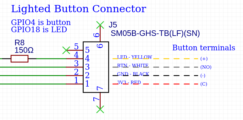
Schematic section for the button connector. Right side shows recommended connections to the lighted button.
If you buy pre-crimped wires, you’ll need to cut the connector on one side off.
For JST connectors, the small notch on the contact aligns with the bottom side of the connector. On the bottom of the connector housing, there are a series of small plastic pins that will raise up as you insert the contact. Once you get the contact fully inserted, this pin will fall back down to lay flush.
To assemble the button:
- Cut pre-crimped JST wires to length
- Following the image above, strip and solder the free end of each wire to the specified terminals on the switch.
- Place a piece of heatshrink over each terminal and shrink.
- (Optional) Twist the wires gently and use small pieces of heat shrink to keep them in a neat bundle.
- Insert the contacts into the JST GH 5 position housing, following the diagram above.
- Mount the button and insert the connector into the plug on the payload divider PCB.
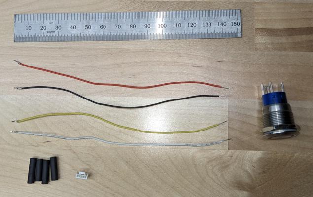
Components of the button assembly. Note that these pictures were taken with the alternative version of the button designed to be mounted on the outside of a Pelican case.
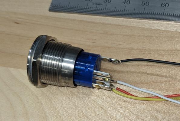
Cables soldered to the terminals of the button