In order to standardize between units, much of the Pi setup is automated or semi-automated. This guide will walk you through the steps of setting up your Pi the way we do. Along the way, there are also links for more information on how to customize this setup. This is an area where you will almost certainly need to customize some aspects of the setup.
Initial setup with cloud-init
Setup of the Raspberry Pi is semi-automated using cloud-init.
Cloud-init customization
The cloud-init setup is controlled by two files: user-data and network-config.
(You’ll use these files a couple of steps down.)
Examples of each are shown below, but you will likely need to modify these to suit your purpose. We have pages on how to customize user-data and network-config.
user-data Example
#cloud-config

# This is the user-data configuration file for cloud-init.
# The cloud-init documentation has more details:
#
# https://cloudinit.readthedocs.io/

system_info:
  default_user:
    name: ubuntu # Allow the default user to shutdown or reboot the system without entering a password (used by our automated scripts)
    sudo: "ALL=(ALL) NOPASSWD: /sbin/poweroff, /sbin/reboot, /sbin/shutdown"

# On first boot, set the (default) ubuntu user's password to "cryosphere"
chpasswd:
  expire: false
  users:
    - name: ubuntu
      password: $6$rounds=4096$aQ7tu0.beL3WAL32$fKxKYvZpY7EMCoxAU1heRomA3v8WvgbqBhhz08QwOtQdlP/DJOP2BThqZFoRW8d2a9PaIKK9BC9NHs1qNnkya1
      type: hash

# Enable password authentication with the SSH daemon
ssh_pwauth: true

# Set a default timezone
timezone: Etc/UTC

## Update apt database and upgrade packages on first boot
package_update: true
package_upgrade: true

## Install additional packages on first boot
packages:
- net-tools
- git
- cmake
- g++
- mosh
- exfat-fuse
- i2c-tools
- rpi.gpio-common
- util-linux-extra
- gpsd
- gpsd-clients

## Write arbitrary files to the file-system
write_files:
- path: /home/ubuntu/initial_setup.sh
  content: |
    #!/bin/bash
    exec > >(tee -a "initial_setup_output.log") 2>&1
    # Miniconda Setup
    wget --progress=bar:force:noscroll "https://github.com/conda-forge/miniforge/releases/latest/download/Miniforge3-Linux-aarch64.sh" -O $HOME/miniconda.sh
    bash $HOME/miniconda.sh -b -p $HOME/miniconda
    cd $HOME
    source .profile
    source miniconda/etc/profile.d/conda.sh
    conda init bash
    # Setup logger environment
    git clone git@github.com:thomasteisberg/uav_radar_logger.git
    # Clone uhd_radar repo
    git clone git@github.com:radioglaciology/uhd_radar.git
    cd uhd_radar
    #git checkout thomas/dask # Uncomment if you want to check out a specific branch other than main
    conda env create -n uhd -f environment-rpi.yaml
    conda activate uhd
    python /home/ubuntu/miniconda/envs/uhd/lib/uhd/utils/uhd_images_downloader.py
    systemctl --user enable radar.service
    systemctl --user enable logger.service
    ifconfig
    sudo reboot
  append: true
- path: /home/ubuntu/.profile
  content: |
    PATH=/home/ubuntu/miniconda/bin:$PATH
    source /home/ubuntu/.bashrc
  append: true
- path: /home/ubuntu/.ssh/known_hosts
  content: |
    github.com ssh-ed25519 AAAAC3NzaC1lZDI1NTE5AAAAIOMqqnkVzrm0SdG6UOoqKLsabgH5C9okWi0dh2l9GKJl
    github.com ecdsa-sha2-nistp256 AAAAE2VjZHNhLXNoYTItbmlzdHAyNTYAAAAIbmlzdHAyNTYAAABBBEmKSENjQEezOmxkZMy7opKgwFB9nkt5YRrYMjNuG5N87uRgg6CLrbo5wAdT/y6v0mKV0U2w0WZ2YB/++Tpockg=
    github.com ssh-rsa AAAAB3NzaC1yc2EAAAADAQABAAABgQCj7ndNxQowgcQnjshcLrqPEiiphnt+VTTvDP6mHBL9j1aNUkY4Ue1gvwnGLVlOhGeYrnZaMgRK6+PKCUXaDbC7qtbW8gIkhL7aGCsOr/C56SJMy/BCZfxd1nWzAOxSDPgVsmerOBYfNqltV9/hWCqBywINIR+5dIg6JTJ72pcEpEjcYgXkE2YEFXV1JHnsKgbLWNlhScqb2UmyRkQyytRLtL+38TGxkxCflmO+5Z8CSSNY7GidjMIZ7Q4zMjA2n1nGrlTDkzwDCsw+wqFPGQA179cnfGWOWRVruj16z6XyvxvjJwbz0wQZ75XK5tKSb7FNyeIEs4TT4jk+S4dhPeAUC5y+bDYirYgM4GC7uEnztnZyaVWQ7B381AK4Qdrwt51ZqExKbQpTUNn+EjqoTwvqNj4kqx5QUCI0ThS/YkOxJCXmPUWZbhjpCg56i+2aB6CmK2JGhn57K5mj0MNdBXA4/WnwH6XoPWJzK5Nyu2zB3nAZp+S5hpQs+p1vN1/wsjk=
- path: /etc/security/limits.conf # Recommended by Ettus https://kb.ettus.com/USRP_Host_Performance_Tuning_Tips_and_Tricks
  content: |
    ubuntu    - rtprio    99
  append: true
- path: /etc/systemd/user/radar.service
  content: |
    [Unit]
    Description=Service to run the radar code on startup

    [Service]
    Type=simple
    WorkingDirectory=/home/ubuntu/uhd_radar/
    ExecStart=/home/ubuntu/uhd_radar/manager/radar_service.sh

    Restart=always
    RestartSec=10

    KillSignal=SIGINT

    [Install]
    WantedBy=default.target
- path: /etc/systemd/user/logger.service
  content: |
    [Unit]
    Description=Service to log data from I2C sensors and automatically shutdown below a voltage threshold

    [Service]
    Type=simple
    WorkingDirectory=/home/ubuntu/uav_radar_logger/
    ExecStart=/home/ubuntu/uav_radar_logger/logger_service.sh

    Restart=always
    RestartSec=60

    KillSignal=SIGINT

    [Install]
    WantedBy=default.target

# Run arbitrary commands at rc.local like time
# These commands are run with root permissions
# If you want commands run as a normal user, put them in initial_setup.sh (see above)
# which is run as the "ubuntu" user (see below)
runcmd:
- chown -R ubuntu:ubuntu /home/ubuntu
- chmod +x /home/ubuntu/initial_setup.sh
- wget -O /etc/udev/rules.d/uhd-usrp.rules https://raw.githubusercontent.com/EttusResearch/uhd/master/host/utils/uhd-usrp.rules
- usermod -a -G i2c ubuntu
- usermod -a -G dialout ubuntu
- usermod -a -G tty ubuntu
- apt remove -y modemmanager
- systemctl stop serial-getty@ttyS0.service && systemctl disable serial-getty@ttyS0.service
- i2cdetect -y 1
- echo "dtoverlay=i2c-rtc,pcf8523" >> /boot/firmware/config.txt
- loginctl enable-linger ubuntu
- mkdir /media/ssd
- chown ubuntu /media/ssd
- chgrp ubuntu /media/ssd
- echo "/dev/sda2  /media/ssd  exfat  defaults,nofail,uid=1000,gid=1000  0  2" | tee -a /etc/fstab
network-config Example
# This file contains a netplan-compatible configuration which cloud-init will
# apply on first-boot (note: it will *not* update the config after the first
# boot). Please refer to the cloud-init documentation and the netplan reference
# for full details:
#
# https://cloudinit.readthedocs.io/en/latest/topics/network-config.html
# https://cloudinit.readthedocs.io/en/latest/topics/network-config-format-v2.html
# https://netplan.io/reference
version: 2
ethernets:
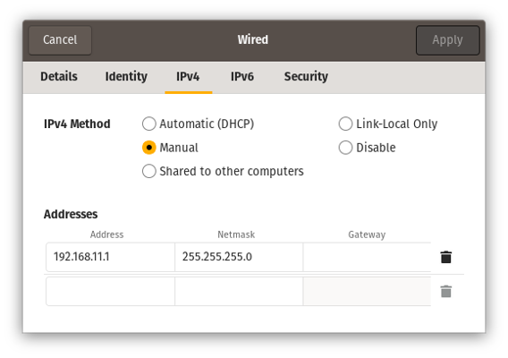
eth0: # Your ethernet name.
dhcp4: no
addresses: [192.168.11.137/24]
gateway4: 192.168.11.1
nameservers:
addresses: [8.8.8.8,8.8.4.4]
wifis:
renderer: networkd
wlan0:
dhcp4: true
optional: true
access-points:
"<YOUR WIFI SSID HERE>":
password: "<YOUR WIFI PASSWORD HERE>"
Imaging your Pi
To start, download the Raspberry Pi Imager tool (or use your preferred software for imaging SD cards). On Ubuntu, you can install it like this:
sudo apt install rpi-imager
For other operating systems, see the website.
Note on selecting a microSD card
Not all (micro) SD cards are the same. Speed and reliability can both vary a lot.
Especially if you plan to store your data to your MicroSD card, you don’t want to mess around with this. Don’t use an SD card that’s off-brand, questionably sourced (i.e. possibly counterfeit), or used.
We use Samsung Pro Plus series MicroSD cards. There are other storage options too. See Other Storage Options for details.
Launch Imager. After clicking on “Choose OS,” navigate through the general purpose
category to find Ubuntu Server 22.04.xx LTS 64-bit. 64-bit is important – 32-bit
will not work.
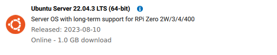
You want Ubuntu Server 22.04 LTS 64-bit.
Insert your MicroSD card and select it as the location to write to.
After imaging is complete, you will see two drives mounted: writable and
system-boot.
Copying cloud-init config files
After customizing the user-data and network-config files (see above),
copy user-data and network-config to the system-boot volume, replacing the
existing files.
Eject the microSD and put it back in the Pi.
Running cloud-init
Your Pi needs an internet connection for this part
Make sure you Pi will have access to the internet before you begin this part. See the networking page for information.Power up the Pi and wait for cloud-init to run.
Within about a minute, your Pi should connect to whatever network interface(s)
are described in network-config and you should be able to find it on the
network. If you setup some sort of key-based authentication (such as by
importing a key from GitHub), it may take an extra couple of minutes for
this to be ready.
After the network setup is complete, you should be able to login over SSH.
In particular, please note that you need to have SSH agent forwarding working. Instructions for this are on that page.
When you first login, cloud-init may not have finished running. To check the status, run:
cloud-init status --long
There are also logs in /var/log/cloud-init-output.log.
To keep an eye on the entire process, you can run:
watch "cloud-init status --long && tail -n 10 /var/log/cloud-init-output.log"
Expect this process to take a few minutes to complete.
Running initial_setup.sh
After the cloud-init process is complete, you’ll also need to run
initial_setup.sh:
./initial_setup.sh
This will log to /home/ubuntu/initial_setup_output.log. It may take around 10
minutes to complete. It will automatically reboot your Pi at the end. If you
don’t want this, feel free to comment out the last line.
Setting up the logger service
More details on the logging service will eventually be here.
For now, if you’re building a Peregrine system, the default setup should be fine.
If you’re building Eyas, first run this command to create a place for logs:
mkdir /media/ssd/logger
And then modify the last line of /home/ubuntu/uav_radar_logger/logger_service.sh
to look like this:
python -u logger.py --shutdown-voltage 11.8 --log-dir /media/ssd/logger/
Replacing 11.8 with an appropriate threshold (in volts) at which to shutdown.
Setting up the radar service
More details on the radar service will eventually be here.
For now, if you’re building a Peregrine system, the default setup should be fine.
If you’re building Eyas, run these commands to create a location for logging data and update the default configuration:
mkdir /media/ssd/radar
cd /home/ubuntu/uhd_radar/config
mv default.yaml default-old.yaml
cp default-eyas.yaml default.yaml
Using overlayroot to protect the file system
Let’s take a quick step back and talk about the problem before we talk about (perhaps drastic) solutions:
MicroSD card corruption is an ongoing challenge for any device (such as the Pi) that boots from a MicroSD card. Most cases can be traced to either (a) junk MicroSD cards or (b) sudden power loss during a write operation.
You can mostly avoid problem (a) by carefully sourcing your MicroSD cards. If you’re considering saving $20 by buying an off-brand MicroSD card or, worse, a possible fake, don’t do it.
Sudden power loss is harder to completely guard against. Ideally, you want to
shutdown your Pi before removing power. This can be done by SSH-ing into it and
running sudo shutdown -h now and waiting about a minute. If you use our
radar systemd service, you can also perform a safe shutdown by pressing and
holding the button for 5 seconds, waiting for the light to turn off, and then
giving it about a minute to fully shut down.
For Peregrine, this should all be good enough.
For Eyas and other longer-term installations, the risk of a battery discharging faster than expected is relatively high.
The first line of defense is the automatic shutdown provided by the logger service that will safely shut everything down when the battery voltage gets too low.
If you have a separate data storage device, such as an external USB-connected SSD, you can go a step further and make your Pi’s MicroSD card read-only.
A utility called overlayroot (which uses OverlayFS)
can be used to make the root filesystem read-only and create an “overlay filesystem”
stored only in RAM. This means that all changes to the MicroSD card file system
are temporary and are lost upon reboot.
This is great for keeping a standardized configuration, but you need to be aware that this means most log files are lost on reboot, any config files on the SD card are lost on reboot, and all radar data you want to keep around must be stored to your external storage device.
You can read a more detailed tutorial about Overlayroot here.
If you’re going to do this, be sure that you’ve tested your setup in advance so you know if the data you want to keep is being stored.
Enabling Overlayroot
If you still want to set this up, it’s quite easy to enable.
Simply edit the last line of /etc/overlayroot.conf to this:
overlayroot="tmpfs:recurse=0"
tmpfs specifies that we want to use a RAM-based filesystem to store the “overlay”
part of the filesystem. recurse=0 says that we want to apply this only to the
/ mount and not to other mounts below that.
(You need to edit this file as root. For example: sudo vim /etc/overlayroot.conf)
Disabling Overlayroot
You can temporarily re-mount the root filesystem to edit things using the built-in utility:
sudo overlayroot-chroot
To exit, just type exit.
If you want to permenantly disable it, just edit the last line of /etc/overlayroot.conf
back to:
overlayroot=""
and reboot.
Step-by-step Installation Guide
The following guide is for Windows, however the steps are the same for Linux and MacOS with some minor tweaks (no need to install WSL, filepaths may differ, etc).
Installing Software
Install Visual Studio Code (VSCode) or another code editor of your choice.
If you are using VSCode, see the additional steps for setting it up here.
Install Windows Subsystem for Linux (WSL). ORCA is developed to be used on a Linux system and requires a Linux terminal such as WSL to run.
From the Start menu, open Powershell and run
wsl --install.Download Conda for Linux. In this guide, we use Miniconda. More details about Conda can be found here. You do not need to open or run the
.shfile at this time.Within VSCode, open a new Ubuntu (WSL) terminal. You may be prompted to create a username and password for the Linux installation. This password will be used any time you run WSL terminal commands with administrator permissions (
sudo).In the WSL terminal, run
bash <path-to-Downloads>/Miniconda3-latest-Linux_x86_64.sh. The path to your downloads folder is typically/mnt/c/Users/<your-username>/Downloads. Accept the default options when prompted, and select yes when asked aboutauto_activate_base, though we will change this setting later.After Miniconda has been installed, close and reopen the WSL terminal, then run
conda listto confirm everything has been installed correctly. You should see a long list of all the installed dependencies printed to the terminal. If you get an error saying conda: command not found, you may be in the wrong terminal or did not install it correctly.We are now going to disable conda from activating every time you open a new terminal. To do this, run
conda config --set auto_activate_base false.
Connecting to GitHub
If you do not intend to modify the code in any way, you may skip this section.
- Create an account on GitHub and sign in.
- Go to the ORCA Repository and click Fork to create your own copy of the code. Name this new repository whatever you want.
- To securely connect your computer to GitHub we will create an SSH key. In the WSL terminal, run
ssh-keygen -t ed25519 -C "your@email.com"and accept the default location. - Create a password that you will input each time you push or pull code from GitHub. When you type the password, no text will appear in the terminal but the password is being logged.
- We now need to copy the public key you just created. When the key was generated, a message should have been printed that says something like Your public key has been saved in /home/
/.ssh/id_ed25519.pub . To view the contents of this public key file, runcat /home/<your-username>/.ssh/id_ed25519.puband copy the full key that is printed to the terminal. - In GitHub. open Settings > SSH and GPG Keys, and click New SSH Key, then paste the key into the appropriate box.
Cloning the Repository
- We now need to install Git in WSL. Run
sudo apt update && sudo apt install git. - To be able to access the code from GitHub on your computer, we have to clone the repository. Go to the fork you just created (or the ORCA repository if you are not creating a fork), and click the green Code button. Within the dropdown, go to the SSH tab and copy the link. It should end in .git.
- Navigate (cd) to whichever folder you would like the code to be copied into, and run
git clone <link-to-repo>. - In VSCode, you can now view the code with File > Open Folder.
Setting up Conda
- We now need to use Conda to install the required dependencies for ORCA.
- Before we create the conda environment, check that GCC is installed by running
gcc --versionin the WSL terminal. If the gcc command is not found, install it withsudo apt update && sudo apt install gcc. - Navigate to the folder containing the code. If you are using a Raspberry Pi to control the SDR, then use
environment-rpi.yamlin the next step instead. Runconda env create -f environment.yaml. - Once the environment is installed, activate it with
conda activate uhd. - Finally, we need to install any remaining dependencies for compiling the code, such as
make. To install them, runsudo apt updateandsudo apt install build-essential.