Beneath are links because the website puts them there, you can ignore them. They are there because they are in the level beneath the Setupguide.
1 - Useful Commands
Cheatsheet for Git, Linux, and Conda commands
Git
Here is also a great website to learn about git processes.
Command
Explanation
cd
Sends you to your home directory
cd ..
Sends you up to the parent directory
cd directoryname
Sends you to the specified directory
ls
Lists all files and directories in your current directory
cat filename.txt
Opens the entire file. You cannot scroll so this is good for short files.
less filename.txt
Opens the file and allows you scroll through
nano filename.txt
Opens the file and allows you to edit
sudo shutdown now
Shuts down the computer
sudo reboot now
Restarts the computer
Conda
2 - ORCA Setup
Aquiring dependencies and setting up the repository on your laptop
The following instructions are for Windows devices. There may be different processes for different OS systems. If you find out how to set ORCA up for different devices, feel free to add to this documentation.
Creating an SSH key and connecting it to GitHub
We will create an SSH key and connecting it to your GitHub. Connecting to GitHub is technically optional but it is highly recommended. Otherwise, you have to manually type in your SSH key to add it the the Raspberry Pi which is difficult and you have a high chance of a typo.
If you’ve already made an SSH key and connected it to GitHub, you can skip this section. If you have no clue what SSH is and want to learn more, you can read Basics of SSH.
To double check that you dont already have an SSH key, open Git Bash terminal and run ls -al ~/.ssh. If you don’t already have one, it will say so. If you don’t have Git Bash already, download it here
We will create an SSH key now. In the Git Bash terminal, run ssh-keygen -t ed25519 -C "your-email@example.com" and accept the default location.
Create a password a memoriable and relatively easy to type password. You will input this every time you pull or push code to GitHub from your terminal, every time you SSH to the pi, and every time you transfer files to and from the pi. This happens a lot, so you may not want your password to be like qv34%3bj2!8ncF and 24 characters long. This however, is entirely up to you as you are the one typing the password. Additionally, please do not make your password as easy as password. A new public key file should be made.
Run cat ~/.ssh/id_ed25519.pub to print out the key to the terminal, and copy it. It starts with “ssh” and ends with your email. You want this whole thing. If you forget the .pub, it prints out your private key, which you do not want to give GitHub!! Do not copy out your private key!
If that command doesn’t work, and you happen to be in the .ssh directory, you can run cat id_ed25519.pub
In GitHub, open settings and go to the SSH and GPG keys tab, and add a new SSH key.
Name this whatever you want and paste the key into the correct field.
If you need more help with making an SSH key, here is a helpful GitHub link
SSH Agent Forwarding
After making your SSH key, you need to add it to your SSH agent on your laptop. First we need the SSH agent to be running.
In powershell run Get-Service -Name ssh-agent.
If it says the status is stopped, run Start-Service ssh-agent.
Run Get-Service -Name ssh-agent again and check it says the status is running.
To add your key, run ssh-add C:/Users/YOUR-NAME/.ssh/id_ed25519. You will need to insert the secure passphrase you made when you originally made your SSH key. It should say “Identity added”.
You can test this by running ssh -T git@github.com. It will say that you have been successfully authenticated, but GitHub does not provide shell access .
Installing dependencies
If you are using a Raspberry Pi, you will also want to get miniconda for the Raspberry Pi. This will be done later once the Pi is up and running. You still want to do this section so you can run the code on your laptop when making plots.
Install WSL (Windows Subsystem for Linux)
From the Start menu, open Powershell and type wsl --install.
Install VSCode (or some other code editor of choice).
If you’re using VSCode, open the Extensions tab and install the following extensions: Python, C/C++, and CMake Tools
Within VSCode, open a new Ubuntu (WSL) terminal.
Open terminal with CTRL + ` .
On the top right of the terminal section there will be name of the current terminal (likely powershell), plus sign, and a dropdown arrow.
Hit the dropdown arrow and there will be an (Ubuntu WSL) option.
Create a username and password for the Linux system if prompted. This password is used when running Linux commands with administrator permissions (sudo).
You will need the Linux x86 Miniconda version, NOT WINDOWS and do not open your downloaded .sh file. Download here. You will need to click the Linux tab to access the correct download files. Save the file in your Downloads folder.
In the WSL terminal, change your location to be your Downloads folder.
You can see your current location on the side
Use cd folder-name to enter a specific folder
Use cd .. to go up a folder
Run bash Miniconda3-latest-Linux-x86_64.sh and accept the default options in the installer (select yes when prompted about auto_activate_base, though we will change this later). Accept yes to the liscense terms. It will take time to load. If you hit enter and a new blank line appears, that means it is loading.
After Miniconda has been installed, close and reopen the WSL terminal. Next to the dropdown arrow where you first opened the WSL terminal is a trashcan to close the terminal.
To ensure it has been installed, run conda list and you should see a list of the installed dependencies printed out.
We are now going to change one of the default settings with the command conda config --set auto_activate_base false
Cloning the Repository
Next we will clone the GitHub repository, so it can be accessed locally.
Go to the ORCA repository and click
the green code button and click open with github desktop
Click the green Code button and within the dropdown go to the SSH tab.
Copy the repository link which should end in .git
In the Git Bash terminal, navigate to whichever folder you would like the code to be copied into (with cd folder-name and/or cd ..), and run git clone link_to_repo.git.
In VSCode, you can now open this folder to see all the code
If you haven’t worked with Git before, read the Basics of Git
Setting up Conda
We now need to use Conda to install the required dependencies for ORCA.
Before we create the conda environment, check that GCC is installed by running gcc --version in the WSL terminal. If the gcc command is not found then install it with sudo apt update and sudo apt install gcc
In the WSL terminal, navigate to the folder you just cloned the code to and run conda env create -f environment-rpi.yaml
Once the environment is installed, run conda activate uhd
Run uhd_images_downloader
The code is now installed and ready to run or modified.
If you already know how SSH works you don’t need to read this. The goal is to gain a basic understanding of what SSH is. This is NOT a tutorial on how to set up SSH.
SSH stands for secure shell. This is another way to connect to other cloud services or devices without needing to login each time. SSH is being used here with GitHub and the Raspberry Pi. You can clone a repository using SSH and you can connect to your Raspberry Pi’s terminal from your laptop using SSH.
Whenever you generate a key on your laptop, it creates both a public and private version. The public version is what you give to things like GitHub or the Raspberry Pi. The private key is what you keep on your laptop and don’t share with anyone.
Whenever you try to connect to something, like GitHub with the SSH key, something happens where the public and private key are compared and verified. Then GitHub is like cool, you’re you, and allows you to clone repositories.
To connect to your Raspberry Pi’s terminal from your laptop, you first give it the public key. After it is connected to the wifi, it is able to copy it from GitHub. Further details are in the setting up your Raspberry Pi page. Then when you try to connect to the Raspberry Pi, the two keys are compared. After verification, you then can access the Pi’s terminal. If verification fails, you can’t access the terminal.
If you already know how Git works you don’t need to read this. The goal is to gain a basic understanding of how to use Git.
Using Git
Git is a version control system that is used to keep track of changes to code, work on separate branches, and collaborate with other developers on the same codebase. It connects your local (offline) code to the remote (cloud) repository on GitHub. Below is basic information on how to use Git.
Cloning and pulling
To initially copy a repository from GitHub, use the git clone <repo-link> (you may need to include the https:// portion of the link or use SSH which is explained above) command as shown above. After you’ve cloned a repository, you can update your local repository with the latest version available on GitHub with the git pull command. When multiple people are working on the same branch, it is important to pull the latest code before pushing anything new.
Comitting Changes
When you have made new changes you want to push to GitHub, you will need to make a commit. First, add all the files you changed using git add -A which adds all modified files. If you only want to add a few specific ones, you can do git add file1.txt file2.txt. The terminal does need to be in the correct folder to add specific files. If the terminal is in a folder above the editted files, you can run git add ./folder/file.txt to add them. Another option is to change the terminal’s location with cd folder.
After adding files, create a new commit using git commit -m "Commit message". To make this commit available on GitHub, push the changes with git push. Git may ask you to explicitly define the upstream branch you are trying to push to, in this case follow the suggestions given such as git push -u origin branchname or git push --set-upstream origin branchname. This process is to link your local branch to a branch on the cloud. You can make multiple commits locally before pushing it to GitHub, or you can push right away after making a commit.
Branches
Git allows you to have multiple branches of the code. Each branch keeps different changes and commits, then the two branches can be merged back together. It is standard practice to make a new branch for each new feature that is being added, as it avoids problems introduced by having multiple partially implemented features conflicting with each other, as well as conflicts introduced by multiple developers working on the same file at the same time. A new branch can be created with git checkout -b branchname. Once the branch is created, you can switch between branches with git checkout branchname (the default branch is called “main”). If changes were made to the main branch after you created your branch and you want to include them in your branch, you can merge the main branch into yours. First make sure you are on your branch (git branch will tell you what branch you are on, to exit hit q), then run git fetch origin and git merge origin/main. You may run into merge conflicts which occur when each branch makes changes to the same lines of code. VS Code has a nice built-in GUI for resolving merge conflicts, which allows you to select which change to make.
VS Code also a different UI to do all of the items mentioned above instead of using a terminal if you want to search it up.
In order to standardize between units, much of the Pi setup is automated or semi-automated. This guide will walk you through the steps of setting up your Pi the way we do. Along the way, there are also links for more information on how to customize this setup. This is an area where you will almost certainly need to customize some aspects of the setup.
Imaging your Pi
To start, download the Raspberry Pi Imager tool (or use your preferred software
for imaging SD cards). Imaging is basically giving the Raspberry Pi an operating system. On Ubuntu, you can install it like this:
sudo apt install rpi-imager
For other operating systems, download the tool from here.
Remember to choose your microSD card carefully as mentioned in hardware options
Launcher the imager
Select what version of Raspberry Pi you are using
Under “OS” select “Other general-purpose OS”
Select Ubuntu
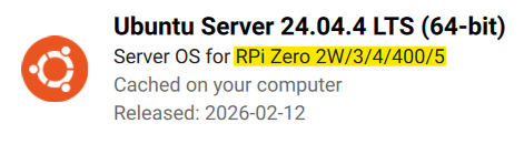
Scroll until you find Ubuntu Server 24.04.xx LTS (64-bit). Make sure you get 64-bit, 32-bit will not work. Also make sure that the Raspberry Pi you are using is supported.
You want Ubuntu Server 24.04 LTS 64-bit and make sure your Pi is supported as shown in the highlight
Insert your SD card if you haven’t already done so, and select it
Skip customization, we will create our own user-data file to insert
Image the SD card
After imaging is complete, you should see a system-boot drive and maybe a writable drive. system-boot is more important.
Can't find system-boot?
If you see a different drive from the SD card that tells you to format it in order to read it, do not format it. The following information is likely Windows specific. If you can’t see the system-boot drive, it is likely because it wasn’t assigned a letter. You need admin privliages to fix this. Hit WIN + X and select “Disk Manager”. You will see the system-boot drive there, it just doesn’t have a letter. Right click on it and assign a letter. Click “add” on the pop up and assign it a letter. The drive should now be visible in your file explorer.
Cloud-init
Setup of the Raspberry Pi is semi-automated using cloud-init.
Cloud-init customization
The cloud-init setup is controlled by two files: user-data and network-config.
(You’ll use these files a couple of steps down.)
Examples of each are shown below, but you will likely need to modify these to suit
your purpose. We have pages on how to customize
network-config and user-data. If you are trying to connect to an enterprise Wi-Fi like a university’s guest wifi, maybe you need to contact OIT to get your device whitelisted. This is how it is at CU Boulder, and I have no idea about how other university’s Wi-Fis work.
user-data Example
#cloud-config# This is the user-data configuration file for cloud-init.# The cloud-init documentation has more details:## https://cloudinit.readthedocs.io/system_info:default_user:name:ubuntu# Allow the default user to shutdown or reboot the system without entering a password (used by our automated scripts)sudo:"ALL=(ALL) NOPASSWD: /sbin/poweroff, /sbin/reboot, /sbin/shutdown"# On first boot, set the (default) ubuntu user's password to "cryosphere"chpasswd:expire:falseusers:- name:ubuntupassword:$6$rounds=4096$aQ7tu0.beL3WAL32$fKxKYvZpY7EMCoxAU1heRomA3v8WvgbqBhhz08QwOtQdlP/DJOP2BThqZFoRW8d2a9PaIKK9BC9NHs1qNnkya1type:hash# Enable password authentication with the SSH daemonssh_pwauth:true# Set a default timezonetimezone:Etc/UTC## Update apt database and upgrade packages on first bootpackage_update:truepackage_upgrade:true## Install additional packages on first bootpackages:- net-tools- git- cmake- g++- mosh- exfat-fuse- i2c-tools- rpi.gpio-common- util-linux-extra- gpsd- gpsd-clients## Write arbitrary files to the file-systemwrite_files:- path:/home/ubuntu/initial_setup.shcontent:| #!/bin/bash
exec > >(tee -a "initial_setup_output.log") 2>&1
# Miniconda Setup
wget --progress=bar:force:noscroll "https://github.com/conda-forge/miniforge/releases/latest/download/Miniforge3-Linux-aarch64.sh" -O $HOME/miniconda.sh
bash $HOME/miniconda.sh -b -p $HOME/miniconda
cd $HOME
source .profile
source miniconda/etc/profile.d/conda.sh
conda init bash
# Setup logger environment
git clone git@github.com:thomasteisberg/uav_radar_logger.git
# Clone uhd_radar repo
git clone git@github.com:radioglaciology/uhd_radar.git
cd uhd_radar
#git checkout thomas/dask # Uncomment if you want to check out a specific branch other than main
conda env create -n uhd -f environment-rpi.yaml
conda activate uhd
python /home/ubuntu/miniconda/envs/uhd/lib/uhd/utils/uhd_images_downloader.py
systemctl --user enable radar.service
systemctl --user enable logger.service
ifconfig
sudo rebootappend:true- path:/home/ubuntu/.profilecontent:| PATH=/home/ubuntu/miniconda/bin:$PATH
source /home/ubuntu/.bashrcappend:true- path:/home/ubuntu/.ssh/known_hostscontent:| github.com ssh-ed25519 AAAAC3NzaC1lZDI1NTE5AAAAIOMqqnkVzrm0SdG6UOoqKLsabgH5C9okWi0dh2l9GKJl
github.com ecdsa-sha2-nistp256 AAAAE2VjZHNhLXNoYTItbmlzdHAyNTYAAAAIbmlzdHAyNTYAAABBBEmKSENjQEezOmxkZMy7opKgwFB9nkt5YRrYMjNuG5N87uRgg6CLrbo5wAdT/y6v0mKV0U2w0WZ2YB/++Tpockg=
github.com ssh-rsa AAAAB3NzaC1yc2EAAAADAQABAAABgQCj7ndNxQowgcQnjshcLrqPEiiphnt+VTTvDP6mHBL9j1aNUkY4Ue1gvwnGLVlOhGeYrnZaMgRK6+PKCUXaDbC7qtbW8gIkhL7aGCsOr/C56SJMy/BCZfxd1nWzAOxSDPgVsmerOBYfNqltV9/hWCqBywINIR+5dIg6JTJ72pcEpEjcYgXkE2YEFXV1JHnsKgbLWNlhScqb2UmyRkQyytRLtL+38TGxkxCflmO+5Z8CSSNY7GidjMIZ7Q4zMjA2n1nGrlTDkzwDCsw+wqFPGQA179cnfGWOWRVruj16z6XyvxvjJwbz0wQZ75XK5tKSb7FNyeIEs4TT4jk+S4dhPeAUC5y+bDYirYgM4GC7uEnztnZyaVWQ7B381AK4Qdrwt51ZqExKbQpTUNn+EjqoTwvqNj4kqx5QUCI0ThS/YkOxJCXmPUWZbhjpCg56i+2aB6CmK2JGhn57K5mj0MNdBXA4/WnwH6XoPWJzK5Nyu2zB3nAZp+S5hpQs+p1vN1/wsjk=- path:/etc/security/limits.conf# Recommended by Ettus https://kb.ettus.com/USRP_Host_Performance_Tuning_Tips_and_Trickscontent:| ubuntu - rtprio 99append:true- path:/etc/systemd/user/radar.servicecontent:| [Unit]
Description=Service to run the radar code on startup
[Service]
Type=simple
WorkingDirectory=/home/ubuntu/uhd_radar/
ExecStart=/home/ubuntu/uhd_radar/manager/radar_service.sh
Restart=always
RestartSec=10
KillSignal=SIGINT
[Install]
WantedBy=default.target- path:/etc/systemd/user/logger.servicecontent:| [Unit]
Description=Service to log data from I2C sensors and automatically shutdown below a voltage threshold
[Service]
Type=simple
WorkingDirectory=/home/ubuntu/uav_radar_logger/
ExecStart=/home/ubuntu/uav_radar_logger/logger_service.sh
Restart=always
RestartSec=60
KillSignal=SIGINT
[Install]
WantedBy=default.target# Run arbitrary commands at rc.local like time# These commands are run with root permissions# If you want commands run as a normal user, put them in initial_setup.sh (see above)# which is run as the "ubuntu" user (see below)runcmd:- chown -R ubuntu:ubuntu /home/ubuntu- chmod +x /home/ubuntu/initial_setup.sh- wget -O /etc/udev/rules.d/uhd-usrp.rules https://raw.githubusercontent.com/EttusResearch/uhd/master/host/utils/uhd-usrp.rules- usermod -a -G i2c ubuntu- usermod -a -G dialout ubuntu- usermod -a -G tty ubuntu- apt remove -y modemmanager- systemctl stop serial-getty@ttyS0.service && systemctl disable serial-getty@ttyS0.service- i2cdetect -y 1- echo "dtoverlay=i2c-rtc,pcf8523" >> /boot/firmware/config.txt- loginctl enable-linger ubuntu- mkdir /media/ssd- chown ubuntu /media/ssd- chgrp ubuntu /media/ssd- echo "/dev/sda2 /media/ssd exfat defaults,nofail,uid=1000,gid=1000 0 2" | tee -a /etc/fstab
network-config Example
# This file contains a netplan-compatible configuration which cloud-init will# apply on first-boot (note: it will *not* update the config after the first# boot). Please refer to the cloud-init documentation and the netplan reference# for full details:## https://cloudinit.readthedocs.io/en/latest/topics/network-config.html# https://cloudinit.readthedocs.io/en/latest/topics/network-config-format-v2.html# https://netplan.io/referenceversion:2ethernets:eth0:# Your ethernet name.dhcp4:noaddresses:[192.168.11.137/24]gateway4:192.168.11.1nameservers:addresses:[8.8.8.8,8.8.4.4]wifis:renderer:networkdwlan0:dhcp4:trueoptional:trueaccess-points:"<YOUR WIFI SSID HERE>":password:"<YOUR WIFI PASSWORD HERE>"
network-config Example for Laptop Mobile Hotspot and Possibly Normal Wifi
# This file contains a netplan-compatible configuration which cloud-init will# apply on first-boot (note: it will *not* update the config after the first# boot). Please refer to the cloud-init documentation and the netplan reference# for full details:## https://cloudinit.readthedocs.io/en/latest/topics/network-config.html# https://cloudinit.readthedocs.io/en/latest/topics/network-config-format-v2.html# https://netplan.io/referencenetwork:version:2renderer:networkdwifis:wlan0:dhcp4:yesaccess-points:"<WIFI SSID HERE>":password:"<PASSWORD HERE>"
If your wifi SSID or password has slashes, it might freak the Raspberry Pi out and the network-config won’t run properly.
After you edit the user-data and network-config files and add them to your SD card. You can now put the card back into the Pi.
# This file contains a netplan-compatible configuration which cloud-init will# apply on first-boot (note: it will *not* update the config after the first# boot). Please refer to the cloud-init documentation and the netplan reference# for full details:## https://cloudinit.readthedocs.io/en/latest/topics/network-config.html# https://cloudinit.readthedocs.io/en/latest/topics/network-config-format-v2.html# https://netplan.io/referenceversion:2ethernets:eth0:# Your ethernet name.dhcp4:noaddresses:[192.168.11.137/24]gateway4:192.168.11.1nameservers:addresses:[8.8.8.8,8.8.4.4]wifis:renderer:networkdwlan0:dhcp4:trueoptional:trueaccess-points:"<YOUR WIFI SSID HERE>":password:"<YOUR WIFI PASSWORD HERE>"
The above configuration sets up a static IP over the ethernet interface. It
also configures 192.168.11.1 as the default gateway. This allows for sharing
an internet connection from a computer over this interface if desired.
The configuration also provides an SSID and password for a WiFi network. In practice,
we configure this to the settings for a phone hotspot that can be used to get
internet when WiFi is not otherwise available. This is also a simpler setup for
getting the Pi on the internet when needed.
Reconfiguring with netplan
By default, network interfaces are configured with netplan. See
the netplan documentation
for more details.
By default, the cloud-init script sets up a static IP of 192.168.11.137, but
you could choose to configure this to something different for each payload box.
Our usual way of connecting is by plugging an ethernet cable into the Pi and
connecting it to a laptop. You can read about
all the networking options here.
Understanding the user-data file and any edits you may want to make
Use this when setting up your Raspberry Pi on initial boot-up.
The default user-data we start from is as shown below. You will likely need to
tweak many of these settings. Descriptions and tips for the most important
sections are below.
Note that this is one of two key configuration files. You can read about
network-config here.
Starting point user-data file
#cloud-config# This is the user-data configuration file for cloud-init.# The cloud-init documentation has more details:## https://cloudinit.readthedocs.io/system_info:default_user:name:ubuntu# Allow the default user to shutdown or reboot the system without entering a password (used by our automated scripts)sudo:"ALL=(ALL) NOPASSWD: /sbin/poweroff, /sbin/reboot, /sbin/shutdown"# On first boot, set the (default) ubuntu user's password to "cryosphere"chpasswd:expire:falseusers:- name:ubuntupassword:$6$rounds=4096$aQ7tu0.beL3WAL32$fKxKYvZpY7EMCoxAU1heRomA3v8WvgbqBhhz08QwOtQdlP/DJOP2BThqZFoRW8d2a9PaIKK9BC9NHs1qNnkya1type:hash# Enable password authentication with the SSH daemonssh_pwauth:true# Set a default timezonetimezone:Etc/UTC## Update apt database and upgrade packages on first bootpackage_update:truepackage_upgrade:true## Install additional packages on first bootpackages:- net-tools- git- cmake- g++- mosh- exfat-fuse- i2c-tools- rpi.gpio-common- util-linux-extra- gpsd- gpsd-clients## Write arbitrary files to the file-systemwrite_files:- path:/home/ubuntu/initial_setup.shcontent:| #!/bin/bash
exec > >(tee -a "initial_setup_output.log") 2>&1
# Miniconda Setup
wget --progress=bar:force:noscroll "https://github.com/conda-forge/miniforge/releases/latest/download/Miniforge3-Linux-aarch64.sh" -O $HOME/miniconda.sh
bash $HOME/miniconda.sh -b -p $HOME/miniconda
cd $HOME
source .profile
source miniconda/etc/profile.d/conda.sh
conda init bash
# Setup logger environment
git clone git@github.com:thomasteisberg/uav_radar_logger.git
# Clone uhd_radar repo
git clone git@github.com:radioglaciology/uhd_radar.git
cd uhd_radar
#git checkout thomas/dask # Uncomment if you want to check out a specific branch other than main
conda env create -n uhd -f environment-rpi.yaml
conda activate uhd
python /home/ubuntu/miniconda/envs/uhd/lib/uhd/utils/uhd_images_downloader.py
systemctl --user enable radar.service
systemctl --user enable logger.service
ifconfig
sudo rebootappend:true- path:/home/ubuntu/.profilecontent:| PATH=/home/ubuntu/miniconda/bin:$PATH
source /home/ubuntu/.bashrcappend:true- path:/home/ubuntu/.ssh/known_hostscontent:| github.com ssh-ed25519 AAAAC3NzaC1lZDI1NTE5AAAAIOMqqnkVzrm0SdG6UOoqKLsabgH5C9okWi0dh2l9GKJl
github.com ecdsa-sha2-nistp256 AAAAE2VjZHNhLXNoYTItbmlzdHAyNTYAAAAIbmlzdHAyNTYAAABBBEmKSENjQEezOmxkZMy7opKgwFB9nkt5YRrYMjNuG5N87uRgg6CLrbo5wAdT/y6v0mKV0U2w0WZ2YB/++Tpockg=
github.com ssh-rsa AAAAB3NzaC1yc2EAAAADAQABAAABgQCj7ndNxQowgcQnjshcLrqPEiiphnt+VTTvDP6mHBL9j1aNUkY4Ue1gvwnGLVlOhGeYrnZaMgRK6+PKCUXaDbC7qtbW8gIkhL7aGCsOr/C56SJMy/BCZfxd1nWzAOxSDPgVsmerOBYfNqltV9/hWCqBywINIR+5dIg6JTJ72pcEpEjcYgXkE2YEFXV1JHnsKgbLWNlhScqb2UmyRkQyytRLtL+38TGxkxCflmO+5Z8CSSNY7GidjMIZ7Q4zMjA2n1nGrlTDkzwDCsw+wqFPGQA179cnfGWOWRVruj16z6XyvxvjJwbz0wQZ75XK5tKSb7FNyeIEs4TT4jk+S4dhPeAUC5y+bDYirYgM4GC7uEnztnZyaVWQ7B381AK4Qdrwt51ZqExKbQpTUNn+EjqoTwvqNj4kqx5QUCI0ThS/YkOxJCXmPUWZbhjpCg56i+2aB6CmK2JGhn57K5mj0MNdBXA4/WnwH6XoPWJzK5Nyu2zB3nAZp+S5hpQs+p1vN1/wsjk=- path:/etc/security/limits.conf# Recommended by Ettus https://kb.ettus.com/USRP_Host_Performance_Tuning_Tips_and_Trickscontent:| ubuntu - rtprio 99append:true- path:/etc/systemd/user/radar.servicecontent:| [Unit]
Description=Service to run the radar code on startup
[Service]
Type=simple
WorkingDirectory=/home/ubuntu/uhd_radar/
ExecStart=/home/ubuntu/uhd_radar/manager/radar_service.sh
Restart=always
RestartSec=10
KillSignal=SIGINT
[Install]
WantedBy=default.target- path:/etc/systemd/user/logger.servicecontent:| [Unit]
Description=Service to log data from I2C sensors and automatically shutdown below a voltage threshold
[Service]
Type=simple
WorkingDirectory=/home/ubuntu/uav_radar_logger/
ExecStart=/home/ubuntu/uav_radar_logger/logger_service.sh
Restart=always
RestartSec=60
KillSignal=SIGINT
[Install]
WantedBy=default.target# Run arbitrary commands at rc.local like time# These commands are run with root permissions# If you want commands run as a normal user, put them in initial_setup.sh (see above)# which is run as the "ubuntu" user (see below)runcmd:- chown -R ubuntu:ubuntu /home/ubuntu- chmod +x /home/ubuntu/initial_setup.sh- wget -O /etc/udev/rules.d/uhd-usrp.rules https://raw.githubusercontent.com/EttusResearch/uhd/master/host/utils/uhd-usrp.rules- usermod -a -G i2c ubuntu- usermod -a -G dialout ubuntu- usermod -a -G tty ubuntu- apt remove -y modemmanager- systemctl stop serial-getty@ttyS0.service && systemctl disable serial-getty@ttyS0.service- i2cdetect -y 1- echo "dtoverlay=i2c-rtc,pcf8523" >> /boot/firmware/config.txt- loginctl enable-linger ubuntu- mkdir /media/ssd- chown ubuntu /media/ssd- chgrp ubuntu /media/ssd- echo "/dev/sda2 /media/ssd exfat defaults,nofail,uid=1000,gid=1000 0 2" | tee -a /etc/fstab
Password-less shutdown
system_info:
  default_user:
    name: ubuntu # Allow the default user to shutdown or reboot the system without entering a password (used by our automated scripts)
    sudo: "ALL=(ALL) NOPASSWD: /sbin/poweroff, /sbin/reboot, /sbin/shutdown"
One of the features supported by the uav_radar_logger utility is to automatically
cleanly shutdown the system if the measured battery voltage drops below a
threshold. To facilitate this, the default user must be able to shutdown the
system without needing additional authentication. This gives permission for the
ubuntu user to call sudo shutdown or sudo reboot without entering a password.
Password authentication
# On first boot, set the (default) ubuntu user's password to "cryosphere"
chpasswd:
  expire: false
  list:
  - ubuntu:$6$rounds=4096$aQ7tu0.beL3WAL32$fKxKYvZpY7EMCoxAU1heRomA3v8WvgbqBhhz08QwOtQdlP/DJOP2BThqZFoRW8d2a9PaIKK9BC9NHs1qNnkya1

# Enable password authentication with the SSH daemon
ssh_pwauth: true
This sets up a default password for the ubuntu user. You should change this to
something else (or disable password authentication completely, if you prefer).
Passwords are stored in a hashed format. You can generate password hashes using
this utility:
mkpasswd --method=SHA-512 --rounds=4096
Timezone
# Set a default timezone
timezone: Etc/UTC
You could set this to other time zones (i.e. `America/Los_Angeles"), but really
it would make everyone’s life easier if you just set your clock to UTC.
Add SSH keys through GitHub
## On first boot, use ssh-import-id to give the specific users SSH access to
## the default user
ssh_import_id:
- gh:thomasteisberg
- gh:albroome
- gh:dfxmay
You can very conveniently enable key-based authentication for specific GitHub
user names. If your username is in here and you have a public key setup with GitHub,
this public key will be imported and you will be able to SSH into your Pi
with no additional setup. You might want to remove us from your list, though. :)
Files
Arbitrary files can be written to the system with cloud-init. Some of these are
important.
initial_setup.sh
- path: /home/ubuntu/initial_setup.sh
  content: |
    #!/bin/bash
    exec > >(tee -a "initial_setup_output.log") 2>&1
    # Miniconda Setup
    wget --progress=bar:force:noscroll "https://github.com/conda-forge/miniforge/releases/latest/download/Miniforge3-Linux-aarch64.sh" -O $HOME/miniconda.sh
    bash $HOME/miniconda.sh -b -p $HOME/miniconda
    cd $HOME
    source .profile
    source miniconda/etc/profile.d/conda.sh
    conda init bash
    # Setup logger environment
    git clone git@github.com:thomasteisberg/uav_radar_logger.git
    # Clone uhd_radar repo
    git clone git@github.com:radioglaciology/uhd_radar.git
    cd uhd_radar
    #git checkout thomas/dask # Uncomment if you want to check out a specific branch other than main
    conda env create -n uhd -f environment.yaml
    conda activate uhd
    python /home/ubuntu/miniconda/envs/uhd/lib/uhd/utils/uhd_images_downloader.py
    systemctl --user enable radar.service
    systemctl --user enable logger.service
    ifconfig
    sudo reboot
  append: true
The initial_setup.sh script grabs copies of our code and sets up the radar and
logging services. This script is intended to be manually run the first time you
SSH into the system. This enables you to use
SSH agent forwarding
to provide any needed GitHub authentication to get the code.
This is also where you would customize the repositories to check out (if, for
example, you’ve forked our code) and where you can pick a branch to automatically
checkout.
Radar and Logger services
- path: /etc/systemd/user/radar.service
  content: |
    [Unit]
    Description=Service to run the radar code on startup

    [Service]
    Type=simple
    WorkingDirectory=/home/ubuntu/uhd_radar/
    ExecStart=/home/ubuntu/uhd_radar/manager/radar_service.sh

    Restart=always
    RestartSec=10

    KillSignal=SIGINT

    [Install]
    WantedBy=default.target
- path: /etc/systemd/user/logger.service
  content: |
    [Unit]
    Description=Service to log data from I2C sensors and automatically shutdown below a voltage threshold

    [Service]
    Type=simple
    WorkingDirectory=/home/ubuntu/uav_radar_logger/
    ExecStart=/home/ubuntu/uav_radar_logger/logger_service.sh

    Restart=always
    RestartSec=60

    KillSignal=SIGINT

    [Install]
    WantedBy=default.target
Two systemd services are used to manage everything. One run the radar code in
its default button-controlled setup. The other runs basic logging of I2C-connected
sensors and handles automatic low-battery shutdown.
Some final setup is done by running arbitrary commands. These are run as the root
user.
One aspect of this you may wish to customize are the last two lines, which add
settings to automatically mount an ExFAT-formatted SSD plugged into the Pi. This
can be (optionally) used as a storage location for radar data.
Testing changes
You may want to test your changes before using them on your Pi. Options for doing
that are described here.
Note that the initial_setup.sh script downloads miniconda for the aarch64
architecture, which probably won’t work on your computer. If you want to test that
part, you’ll need to change this.
Options for connecting to the Raspberry Pi in order to transmit desired data or set parameters.
Connecting to the Pi
We will be using SSH to connect your laptop to the Pi. There there many ways to SSH, but before doing any SSH, you need to use direct control on the Pi to add the neccessary information to allow for SSH.
Below are the different types of SSH options you can choose from after you get the direct control set up. You do not need to do all three, just pick one you like.
Type
Explanation
SSH over ethernet
You will directly connect your laptop to the Pi via an ethernet cable and share your computer’s internet access with the Pi. You can SSH into the Pi even if your laptop isn’t connected to the internet (I think). This method seems to cause some issues if you’re using a Mac and University Wi-Fi.
SSH over Wi-Fi
The Pi connects to a Wi-Fi network for interent access. If your laptop is connected to the same Wi-Fi, you’ll be able to SSH into the Pi.
SSH with the Pi acting as a hotspot
The Pi acts like a hotspot and emit’s its own kind of Wi-Fi that your laptop can connect to. This then allows you to SSH into the Pi. Your laptop won’t have internet access while it’s connected to the Pi.
Direct Control
This is the process to get the IP address of the Pi and import your public SSH key.
This method requires a monitor and keyboard, cannot be used to share files between a laptop and the Pi, and is more difficult to use. However, we need to use this, mainly to import your SSH key. This is also useful in case the network-config isn’t working. Direct control allows you to edit the file that controls this.
To access the Pi’s terminal directly you will need:
Raspberry Pi 5
Pi Power Supply (plugged into wall)
Monitor (plugged into wall)
HDMI to Micro-HDMI cable
Keyboard
Ethernet cable connected to a router (or ethernet port on the wall of the lab) or just connect the Pi to wifi
Simply connect the ethernet (or just use WiFi), micro-HDMI, keyboard, and power supply to the Raspberry Pi. When it boots, you will see the cloud-init running a bunch of things and the Pi’s Ubuntu Server terminal on the monitor.
If the Pi get stuck on a boot page and keeps cycling through booting through USB-MSD, SD, and NVME, it can’t find the boot files. You may have imaged the SD card for something that doesn’t support the type of Pi you have so you’ll have to reimage it. If you have a small light on your Pi, you may have a tiny button next to it which you can hold to power it off.
Running Cloud-init
Power up the Pi and wait for cloud-init to run.
Within about a minute, your Pi should connect to whatever network interface(s)
are described in network-config and you should be able to find it on the
network. If you setup some sort of key-based authentication (such as by
importing a key from GitHub), it may take an extra couple of minutes for
this to be ready.
After the network setup is complete, you should be able to login over SSH if you edited the user-data file to import your SSH key. However if that process failed, then you’ll have to manually import your SSH key.
In particular, please note that you need to have SSH agent forwarding working on your laptop.
You should have already done this under ORCA Setup when you first made your SSH key. You can test that everything is working by running ssh -T git@github.com on your laptop.
When you first login to the Pi, cloud-init may not have finished running. To check the status, run:
cloud-init status --long
There are also logs in /var/log/cloud-init-output.log (you can read with cat or less).
To keep an eye on the entire process, you can run:
watch "cloud-init status --long && tail -n 10 /var/log/cloud-init-output.log"
Expect this process to take a few minutes to complete.
Initial Setup
When you are able to start running commands, run ./initial_setup.sh. This will log to /home/ubuntu/initial_setup_output.log. It may take around 10 minutes to complete. It will automatically reboot your Pi at the end. If you don’t want this, feel free to comment out the last line. If you don’t know where this line is, it is fine to just leave it to reboot.
After this process finishes running, run ping 8.8.8.8 to test if it is connected to wifi/ethernet. If the Pi isn’t connected, it will say “Network is unreachable”. If the Pi is connected, it will start detecting bytes sent by the address. Hit CTRL + C to stop the pinging. It will then give you a report of how much loss there was. You want to have 0 loss.
Not connecting to your wifi/ethernet?
If the Pi isn’t connecting to the wifi, the network-config file might not be formatted properly. One issue that I ran into was using “wlp2s0b1:” instead of “wlan0” under the “wifis:” section. If you run ip link it will list the different formats that it is looking for. In my case, it was looking for “wlan0” for wifi or “eth0” for ethernet.
Here is how to edit your network-config files without having to take the SD card out.
Run ls /etc/netplan/. It should show a .yaml.
Run sudo nano /etc/netplan/FILENAME.yaml. This allows you to open and edit the file.
Change whatever you need to, then hit CTRL + X, then y, then hit enter. This saves your edits.
Run sudo netplan apply to apply these changes
Try pinging 8.8.8.8 again to see if is connected now
You may need to run sudo reboot
You can log in and run commands directly with the keyboard (no mouse inputs). There is no way to scroll up through this terminal however, so if you want to be able to read a long output from a command you must pipe it into a file (ex. python run.py >> terminal_output.txt), then read the text file using nano.
Importing Your SSH Key
You don’t need to do this to SSH into the Pi. I believe this is for if you edit the UHD_radar code on the Pi and try to push it to GitHub. The simplest method is to first add the key to your GitHub account, then import it onto the Pi from there. If you don’t want to set up GitHub, you can add the key directly with a little extra work (though you may have typos which can make it difficult!).
With GitHub:
You should have already added the SSH key to your GitHub account.
Run ssh-import-id gh:<your-github-username> on the Raspberry Pi with the direct control.
If you haven’t yet added your key to GitHub, do the following:
Create an account on GitHub and sign in.
In GitHub, open settings and go to the SSH and GPG keys tab and add a new SSH key.
Name this key whatever you want and paste the key into the correct field.
Log into the Pi using the direct control method above.
Run ssh-import-id gh:<your-github-username>.
Without GitHub:
Log into the Pi using the direct control method above.
Open the authorized keys file with sudo nano ~/.ssh/authorized_keys.
Manually copy your key (starts with ssh-ed25519, ends with your email) into the file
Hit Ctrl+X followed by Y, then Enter to save the changes.
You should now have permission to SSH into the Pi from your laptop using one of the following methods (wifi or ethernet).
Modify your ~/.ssh/config file (use nano ~/.ssh/config) and add an entry like this enabling SSH agent forwarding (or don’t, you likely already set up SSH agent forwarding on your laptop so I don’t think you need to do this. I didn’t do this and it worked fine for me):
Host 192.168.11.137
    HostName 192.168.11.137
    User ubuntu
    ForwardAgent yes
Note that if your username or host IP address is different, you should adjust it accordingly.
Remote host identification has changed
If you use the same static IP for multiple Pi’s (which, presumably, you only
ever use one of at a time), you may encounter an error stating:
@@@@@@@@@@@@@@@@@@@@@@@@@@@@@@@@@@@@@@@@@@@@@@@@@@@@@@@@@@@
@    WARNING: REMOTE HOST IDENTIFICATION HAS CHANGED!     @
@@@@@@@@@@@@@@@@@@@@@@@@@@@@@@@@@@@@@@@@@@@@@@@@@@@@@@@@@@@
IT IS POSSIBLE THAT SOMEONE IS DOING SOMETHING NASTY!
Someone could be eavesdropping on you right now (man-in-the-middle attack)!
It is also possible that a host key has just been changed.
This is because your computer thinks its connecting to a different Raspberry Pi.
You can manually add the fingerprint for the currently connected Pi like this:
(This would be a bad idea to do at random for a remote computer. I’m assuming
here that you’ve just plugged in a new Pi right in front of you and you
know exactly why you’re getting this error. You should only have to do this once
per new Pi.)
General Network Tip
If you ever are struggling and Google another tutorial that uses dnsmasq or dhcpcd, check if your Pi uses NetworkManager!!! It is a lot easier to use than the two mentioned above (in my opinion). The newer Raspberry Pi’s use this and ignore the dnsmasq and dhcpcd.
SSH over Ethernet:
This is a good method because the Pi is not required to be connected to a router or Wi-Fi network. However, it does take a bit of setup the first time. This method can be good if you are outside with no access to internet. There is also the SSH over Hotspot method which is also good when you are outside and you won’t need ethernet cables.
For this method, you will need:
Laptop connected to Wi-Fi
Raspberry Pi 5
Pi Power Supply (plugged into wall)
Ethernet cable
Ethernet to usb-c adapter (if your laptop doesn’t have an ethernet port)
Plug the power supply into the Pi and plug one end of the ethernet cable into the Pi, and the other into your laptop.
Connect your laptop to any Wi-Fi network.
If your laptop’s public SSH key is not already on the Pi, see the section above for how to add it. (Using direct connect)
If this is your first time setting up this method, you will now need to enable internet sharing on your laptop. If you have done this before, then skip this step.
a. Windows:
i. Open Control Panel and go to the Network section.
ii. Find the Wi-Fi connection and right click on it, then go to Properties.
iii. At the top, click on the Sharing tab.
iv. Check “Allow other network users to connect…”
v. In the dropdown, select “Ethernet2” (not the ethernet for WSL).
vi. Apply the changes.
b. Linux:
i. Install Network Manager Command-line Interface (nmcli) with sudo apt install network-manager .
ii. Find the connection name with nmcli con show . Find the entry with type ethernet, it should have a name like “Wired connection 1”.
iii. Run nmcli con modify “Wired connection 1” ipv4.method shared .
If you are on Linux, run nmcli con up “Wired connection 1”
Find the Pi’s IP address on your local subnet.
a. If you are on Windows, open PowerShell and run arp -a. You should see an interface for 192.168.137.1 and within that section should be an IP address that starts with 192.168.137 and ends with something other than .0 or .1 (ex. 192.168.137.27).
b. If you are on Linux, then Pi #1 always has the IP 10.42.0.10, and Pi #2 always has the IP 10.42.0.20. If for some reason you cannot find the IP, confirm the subnet is 10.42.0 by running ip a . Under the enxc… section should say “state UP” and you should see “inet 10.42.0.1/24”. You can then scan the subnet to find the pi by running nmap -sn 10.42.0.1/24 and looking for a device that’s not 10.42.0.1. You may need to restart the Pi and give it a minute to boot.
Run ssh ubuntu@<pi-ip-address> to connect to the Pi. You can now run commands on the Pi, and transfer files to and from your laptop using SCP (will be explained below).
SSH over Wi-Fi:
This method is nice as it requires less cables and can be used for connecting multiple devices, however you will have to use one of the other methods such as SSH over Ethernet initially to find the Pi’s internet IP address.
You might be able to just run ssh ubuntu@<pi-ip-address> on your Pi to SSH connect. If you chose a different username than ubuntu, than replace the command with that. The direct connect and internet connection should already exist since you needed them previously to import your GitHub key. You can get your Pi’s IP address by running hostname -I or ip a (in my opinion, using hostname -I is easier cause you don’t need to hunt for the ip info). If you chose a different login username, replace ubuntu with that.
For this method, you will need:
Laptop connected to Wi-Fi
Raspberry Pi 5
Pi Power Supply (plugged into wall)
Ethernet cable connected to a router (or to the ethernet port on the wall of the lab) if not connecting the Pi to Wi-Fi
Plug the ethernet and power cable into the Pi and turn it on. Or if the Pi is connected to Wi-Fi just leave it as is.
If you do not know what the Pi’s current IP address is, you must first use the Direct Control method above to get access to the terminal. You can run hostname -I and it will print out the IP address. Another way is when the Pi first boots, system information is printed to the terminal. In the bottom right corner of this message, you should see a section that says “IPv4 address for eth0 (or wlan0): 128.138.189.xxx”. You can also find the IP address by running ip a and looking for the address under the eth0 (or wlan0). This address may change each time the Pi is reconnected to the internet. This means you will consistently need direct control to see the IP address unless you set a static IP address. Information on how to do this is below.
Connect your laptop to a wifi network.
Check if you can find the Pi over the internet by running the command
ping -c 1 your.pi.ip.address. On Windows, this must be done in PowerShell with admin privileges, not WSL. If it says 0 packets received, then either the IP address is incorrect, or you are not on the same network as the Pi.
If your laptop’s public SSH key is not already on the Pi, see the section above (Importing Your SSH Key section) for how to add it.
Run ssh ubuntu@your.pi.ip.address to connect to the Pi. If you chose a different login username, replace ubuntu with that. You can now run commands on the Pi, and transfer files to and from your laptop using SCP (see below).
If you SSH into your pi from your laptop, you can type exit or logout to turn your powershell back to normal.
SSH with Pi acting as Hotspot:
This method is good for the outdoors where there is no Wifi/internet connection. It allows you to SSH into the Pi without internet connection, similar to SSH over ethernet, but you also won’t need an ethernet cable. If you use this method, the Pi will not be able to access a Wi-Fi internet connection at the same time, so you won’t be able to clone the repository or pull from the repository. This setup will require direct control, but afterwards you won’t need direct control again.
For this method, you will need:
Laptop
Raspberry Pi 5
USB keyboard connected to the Pi (direct control)
Monitor connected to the Pi (direct control)
Pi Power supply
This method uses NetworkManager and your Pi’s connections need to be controlled with NetworkManager. Check if your netplan’s renderer is NetworkManager, if not, change it to NetworkManager.
Run ls /etc/netplan/. It should show a .yaml.
Run sudo nano /etc/netplan/FILENAME.yaml. This allows you to open and edit the file.
Change whatever you need to, then hit CTRL + X, then y, then hit enter. This saves your edits.
Run sudo netplan apply to apply these changes
Try ping 8.8.8.8 again to see if is connected now. Hit Ctrl + C to stop the pinging and check that there is no packet loss.
You may need to run sudo reboot
Run sudo apt update and sudo apt update -y
Run iwconfig to see the names for the different connection tools. We want the wifi one which is commonly wlan0 but it may not be the same for your Pi. It will be the one with information of IEEE and ESSID
DEVICE is the name of the wifi device (commonly wlan0). SSID is the name of the broadcast of the Pi. It will be what your laptop connects to. PASSWORD is the password for the connection. Run sudo nmcli d wifi hotspot ifname DEVICE ssid SSID password PASSWORD
You can check that it has been created by running nmcli connection show. It will look something like this
NAME                UUID                                  TYPE      DEVICE
Hotspot             59f9160c-b49f-47a2-ac54-87987f743df2  wifi      wlan0
Wired connection 1  9d27eb3e-7657-3a54-ad8a-344cb4bb56e3  ethernet  eth0
lo                  a54edcc4-0ffa-4090-a2b3-081905aee1c5  loopback  lo
preconfigured       6e07c33c-9764-4145-af3f-49875c8a9342  wifi      --
If you are connected to wifi, you will see that at the top with the wlan0 device while Hotspot’s device will be blank.
To swap to the Hotspot run nmcli connection up "Hotspot" and to swap back to your wifi replace Hotspot with whatever the name is for your wifi connection. While swapping connections the Pi may freak out and print an error along the lines of brcmfmac: brcmf_set_channel: set chanspec fail, reason -52. This happens whenever the Pi loses connection and isn’t a big issue.
If the putting the hotspot up fails with an error of Connection: activation failed: IP configuration could not be reserved try the following steps
Run sudo nmcli connection modify "Hotspot" ipv4.method shared
Run sudo systemctl stop dnsmasq
Run sudo systemctl restart NetworkManager
Run sudo nmcli connection up "Hotspot"
If this works now, the problem is likely dnsmasq so we need to turn it off permenantly so it won’t turn back on and break the Hotspot when you reboot the Pi.
Run sudo systemctl disable dnsmasq
Run sudo systemctl mask dnsmasq
Run sudo reboot
Now if you run systemctl status dnsmasq it should say that it inactive (dead)
Since you rebooted the Pi, you may need to turn on the hotspot again with nmcli connection up "Hotspot". It should say succesfully activated and you should see the Pi’s hotspot when you open your wifi connections on your laptop. You can now connect to this.
Run ipconfig on your laptop’s powershell after connecting (may be a different command if not on a windows device) and look at the IP address after Default Gateway under the Wi-Fi section. This is the IP address of the PI.
Run ssh ubuntu@your.pi.ip.address to SSH into the Pi.
The next steps are optional but makes it so your Hotspot will be the default connection your Pi does. This makes it so if you are outside and need to connect to the Pi, you can do so immediately without needed direct control to swap the network connection from wifi to the hotspot. The default connection for the Pi seems to be Wi-Fi.
Run sudo nmcli connection modify "Hotspot" connection.autoconnect true
Run sudo nmcli connection modify "Hotspot" connection.autoconnect-priority 100
Run sudo nmcli connection modify "wifi connection" connection.autoconnect-priority 10 Rename “wifi connection” to whatever the name of your wifi connection is. You can check what it is with nmcli connection show. The first autoconnect priority is the higher number.
Now if you reboot the Pi, it will automatically open the hotspot first.
Setting Static IP Addresses
Setting a static IP address makes it very convenient because you won’t need to use direct control to see the Pi’s IP address everytime you want to SSH into it.
Setting a static IP address when the Pi connects to wifi
Run hostname -I to show your current IP. You can use the same one or don’t.
Run ip r | grep default and check the IP that is after the word via. That is your default gateway.
Run nmcli connection show to find the name of your wifi connection
or you can put them all in the same line if you don’t put any slashes
5. Turn off the connection with sudo nmcli connection down "wifi connection"
6. Turn back on the connection with sudo nmcli connection up "wifi connection"
7. Now if you do hostname -I it should be the static IP address you chose and you can ssh to it with this IP address
Bugging SSH connection?/Wi-Fi connection
If the wifi static IP address bugs out and you can’t ssh into the Pi OR the Pi stops connecting to the internet (can’t ping google.com or 8.8.8.8), try restarting the Pi. Also try setting the ipv4.method back to auto, restart it, and back to manual. Do this by running the following commands.
sudo nmcli connection modify "wifi connection" ipv4.method auto
sudo reboot
I haven’t figured out what is causing this so if you do figure it out feel free to add to the documentation!
Setting a static IP address when the Pi acts like a hotspot
Swap back to using your hotspot connection with nmcli connection up "Hotspot"
Run hostname -I to check your current IP address. You can chose this to be your static IP address.
Run sudo nmcli connection modify "Hotspot" ipv4.addresses static.ip.you.chose/24 do not leave out the /24.
Turn on and off the hotspot connection with nmcli connection down "Hotspot" and nmcli connection up "Hotspot"
The IP address should now be static so you no longer have to check the Pi’s IP address with ipconfig whenever you connect to the hotspot.
Now you won’t really need direct connection to control the PI because you can always SSH into it from elsewhere. When you SSH into the Pi, you are still able to swap the connection you just need to add sudo to the front. Example sudo nmcli connection up "wifi connection".
Cloning the Repository onto the Pi
You need to be connected to the internet for this to work. Run git clone https://github.com/username/repositoryname to add the uhd-radar github repository to the Pi. If you don’t have the https:// it won’t work. Using SSH (the link that ends with .git) also won’t work because your Pi doesn’t have your laptop’s private key. Don’t give your Pi your private SSH key.
Transferring files to and from the Pi:
The Raspberry Pi 5 unfortunately does not support data transfer (USB OTG) over its USB 3.0 ports, only the USB C port which we currently use for power. Fortunately, we can make use of the SSH connection to send files to and from the Pi using SCP and/or GitHub.
If you have committed changes to the code and pushed them to GitHub, you can just checkout the correct branch and run git pull on the Pi to see them. However, if you are debugging or making small changes to a file that aren’t worthy of a commit, you can send files directly with SCP (secure copy protocol) by running the following command on your laptop.
Send a single file with scp <my-file-path> ubuntu@<pi-ip-address>:<pidirectory-path>
The "." in windows and the "~" in ubuntu act the same way. They both make it start in the home directory so you don’t have to type all of it out. The "." for windows puts you in C:/Users/YourName and the "~" for ubuntu puts you in /home/AccountUsername.
You can also send a whole folder with scp -r <my-directory-path> ubuntu@<piip-address>:<pi-directory-path>
To send files from the Pi back to your laptop, reverse the two arguments ensuring the first is one or more files, or directory, and the second is a directory for where the file should go.
This pulled from /home/username and put it in C:/Users/Name/Downloads
If you push or pull a file that has the same name in the other device, the new file pushed/pulled will overwrite the old file.
When using these commands, you are typing them on your laptop powershell. You are either pushing from your laptop to the Pi, or you are using your laptop to pull from the Pi. You can also push from the Pi but that’s a different command.
Installing Miniconda
First go to Anaconda’s website and scroll to the bottom to download Miniconda. You will want the Linux 64-Bit ARM64 version.
Once the file is downloaded, you will want to use SCP to get the file onto the Pi. Make sure you have connected to the Pi using SSH. The command might look something like scp .\Downloads\Miniconda3-latest-Linux-aarch64.sh ubuntu@192.168.137.131:~/.
Within the Raspberry Pi’s terminal, run bash location-to-file/Miniconda3-latest-Linux-aarch64.sh and accept the default options in the installer (select yes when prompted about auto_activate_base, though we will change this later)
After Miniconda is installed, reboot the Raspberry Pi with sudo reboot now
To ensure it has been installed, run conda list and you should see a list of the installed dependencies printed out.
We are now going to change one of the default settings with the command conda config --set auto_activate_base false
Walkthrough of different tests and instructions for running the code.
Indoor Testing
While indoors, make sure not to transmit any signals with the antenna. Only transmit into the spectrum analyzer or in a loopback configuration to the SDR.
Before doing any testing in a loopback configuration, use the spectrum analyzer to confirm that the transmitted power is less than the maximum input power the SDR can handle.
When connecting any SMA cable, make sure to hold the cable and connection point still while you connect it so that the cable does not spin as you tighten the nut, as this can cause damage to the pin. Tighten the nut using the SMA torque wrench (the wrench will bend when the proper tightness is reached).
Spectrum Analyzer Test
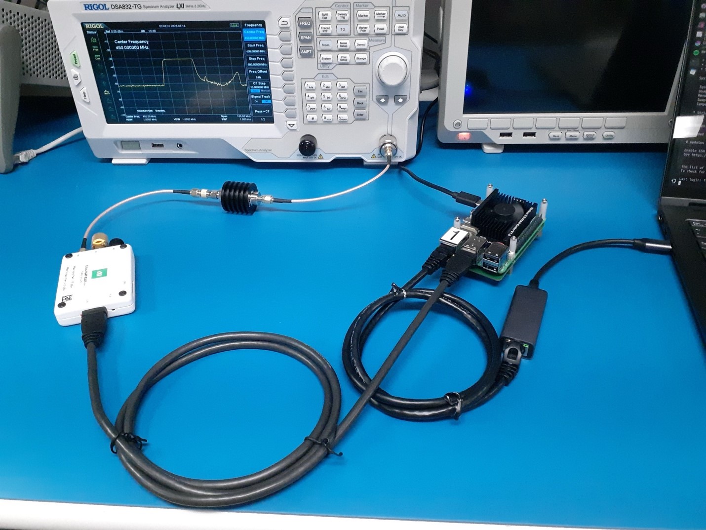
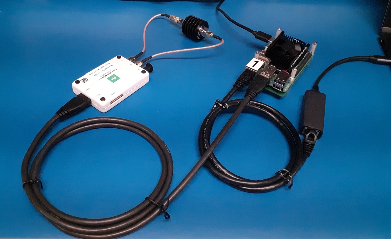
To test the program with the spectrum analyzer, you will need the following equipment:
b205mini SDR
USB 3.0 Micro B cable (connecting SDR to Pi)
Raspberry Pi 5
Raspberry Pi 5 Power Supply (USB C)
Ethernet cable (connecting Pi to Laptop)
Ethernet to USB C adapter (if your laptop doesn’t have ethernet)
30 dB inline attenuator
2 SMA male-male cables
SMA female-female adapter (or replace one of the male-male cables with a male-female cable)
SMA torque wrench
SMA female to N-Type male adapter (probably plugged into the spectrum analyzer RF Input port already)
Spectrum Analyzer (Rigol DSA832-TG)
50 Ohm Load (Found in the Calibration Kit F604MS)
Process
Ensure the blue ESD mat is properly grounded, and there are no food or drinks nearby.
Carefully take the 50 Ohm Load out of the calibration kit box. Be very careful while handling this piece of equipment.
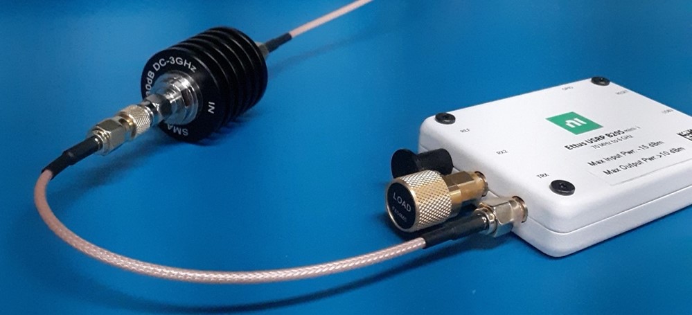
Connect 50 Ohm Load to the “RX2” port on the SDR, ensuring that the load does not spin while the nut is being tightened. Tighten it using the torque wrench.
Connect this cable to the SMA female-female adapter.
Connect the SMA female-female adapter to the “IN” port on the 30 dB attenuator.
Connect the other SMA cable to the “OUT” port on the 30 dB attenuator.
Connect this SMA cable to the SMA female to N-Type adapter.
Connect the SMA female to N-Type adapter to the “RF Input” port on the spectrum analyzer if it is not already connected. Take special care that the adapter does not spin while connecting it to this port.
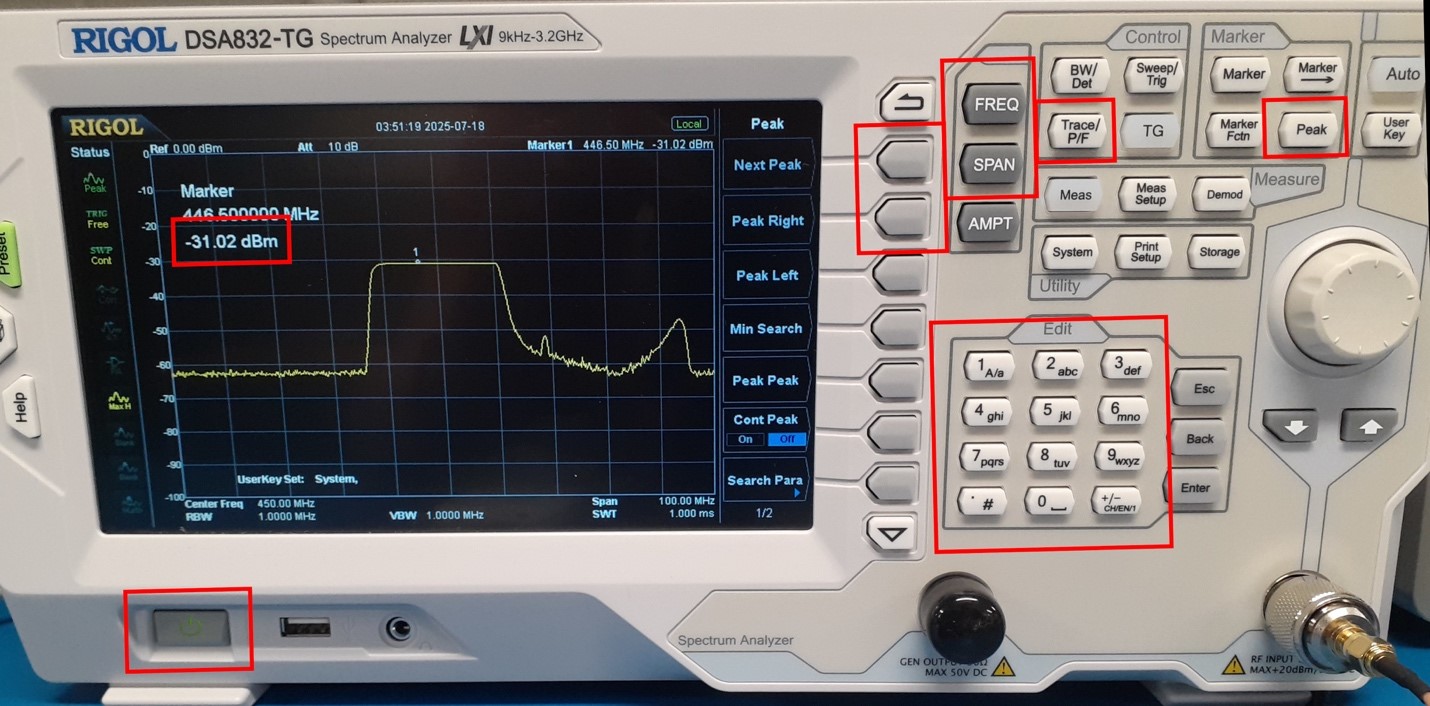
Turn on the spectrum analyzer.
Set the Spectrum Analyzer’s frequency to the chirps’ configured center frequency.
Set the span of the spectrum analyzer to a bandwidth that allows you to see your full chirp in detail.
Configure your spectrum analyzer to see the maximum value when sampled.
Follow the steps in the sections above to connect your laptop to the Pi and get all the code ready to run on the Pi.
Plug the USB 3.0 Micro B cable into one of the blue USB ports on the Pi and plug the other end into the SDR.
Follow the Running the Code section below on how to run the program.
When the code is running, you should see the transmissions appear on the spectrum analyzer. To see the peak transmitted power, press “Peak”. Ensure that this value is less than the SDR’s max input power before doing any loopback or outdoor testing.
Since the SDR is not receiving any samples, you will see receiver errors printed to uhd_stdout.log, and rx_samps.bin will be empty.
Loopback Test
To get any actual data from the SDR, we must both transmit and receive signals by connecting the SDR to itself in a loopback configuration.
Before running the program in this configuration, make sure that you have tested your current code and config settings with the spectrum analyzer method above, and that the peak power is less than the SDR’s max input power (-15 dBm)!
When connecting the b205mini to itself, you should always use a 30 dBm attenuator!
Follow the steps in the Spectrum Analyzer section above to set up the hardware and test it with the spectrum analyzer. Confirm that the program works and the peak power is less than -15dBm.
Stop all transmissions, and do not transmit again until everything has been reconnected. You can unplug the SDR from the Pi to ensure this cannot happen.
Disconnect the SMA cable from the adapter on the spectrum analyzer.
Carefully disconnect the 50 Ohm Load and place it back in the box.
Connect the SMA cable to the “RX2” port on the SDR.
Plug the SDR back into the Pi if you disconnected it previously.
Follow the Running the Code section below to run the program.
Running the Code:
Now that you’re connected to the Pi and have hardware set up, you can run the code with the following commands. Steps 2 through 5 and step 7 only need to be run the first time.
run cd uhd_radar/
run conda env create -n myenvironmentname -f environment.yaml This makes your conda environment. -n myenvironmentname is optional, the default name specified in environment.yaml is uhd. If you are setting an environment up on a Raspberry Pi, we recommend using environment-rpi.yaml instead. This version includes additional dependencies used by manager/uav_payload_manager.py, a helper script designed to run only on Raspberry Pi-based radar instruments.
run sudo apt install make and sudo apt install cmake
run uhd_images_downloader
run uhd_find_devices to check that your SDR is connected. You don’t have to run this.
run conda activate uhd
run make hardware-test and make software-test (if you made any changes to the default file, it will fail a software-test because it is looking for the default config settings)
Check your config settings are set correctly with nano config/<your-file>.yaml (you may want to make a copy of the default.yaml file with cp filename-you're-copying name-of-new-file) Read here to learn about configuration options.
If you are using the B205-mini, make sure the following values in RF0 (not RF1) section are set:
tx_gain should not exceed ~80 dB
rx_gain should not exceed 76 dB
tx_ant should be set to "TX/RX"
rx_ant should be set to "RX2"
transmit should be set to True
run python run.py config/<your-file>.yaml
If you have num_pulses set to -1, then you must stop the program with Ctrl+C
Helpful tip
If you are going to be running a lot of different tests, you probably want to make a table to keep track of which saved file relates to what sort of test.
Common error
If you see an error that says L[1784219558.637] [ERROR] (Chirp 3515) Receiver error: ERROR_CODE_LATE_COMMAND, this is normal. The SDR will just retry sending a chirp since that chirp failed. The number of errors is also random. When you run the same config file sometimes you’ll get more or less late errors.
If you want more information on how the code works, check out the Runtime Overview
Plotting Data
There are two main files you can run to plot your received data. You can run test_loopback.py (under /test_scripts in /postprocessing) or plot_samples.py . At the moment, plot_samples.py and test_loopback.py do not seem print the correct distance in the terminal for my setup. Not sure if it will be different for someone else. test_loopback.py graphs the matched filter version which will show peaks at the correct distance which makes it better than the plot_samples.py script.
Running test_loopback.py
This code is currently only on the gaby-branch branch in the uhd_radar Github. For the loopback test to work correctly, you will need to edit the zero_sample_idx, cable_length, and coax_length which are in the loopback_testing.py file.
This is how to edit the zero_sample_idx. You need to first run the code so you can manually check what the zero sample is.
To view the output data, transfer the desired data files to a laptop (typically the config.yaml and _rx_samps.bin file), ensure the PLOT section has been copied to the config file (it can be found in synthetic-config.yaml) and update the parameters in that section to match the names of the trial you wish to view.
Fun fact!
rx_samps.bin is a binary file (.bin stands for binary), so if you try to open and read it in your powershell, it’ll probably crash! But it does look cool to see a bunch of random symbols sprint past your screen.
The zero sample index is easiest to see if you have the rectangular chirp window (once you find this sample, you’re free to use other chirp windows. The sample index will remain the same as long as the sample rate is the same).
After running the loopback test with short SMA cables, scp the _config.yaml and _rx_samps.bin files from your Raspberry Pi onto your laptop. You want to save these in your branch/clone of the uhd_radar code under the data folder.
Open the WSL terminal (you can do this in VSCode, hit CTRL + `, and use the dropdown arrow to change the terminal type to WSL)
Activate the conda environment with conda activate environment-name. You should already be in your uhd_radar folder but if not, cd into it
Run python postprocessing/test_scripts/test_loopback.py data/timestamp_config.yaml where timestamp is edited to whatever config file you have saved in data.
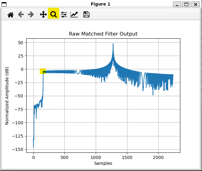
The first graph that appears is the chirp, you want to close this to allow the next graph to appear. The next graph will be matched filter, also close this.
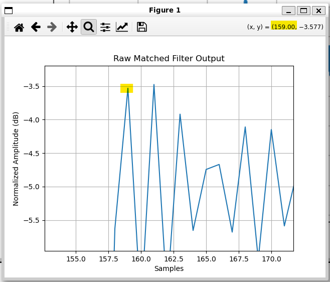
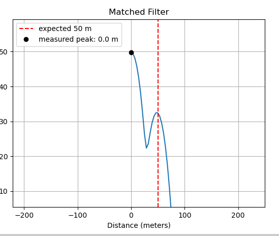
Here is an example of what the graph will look like. You want to use the magnifying glass and zoom in on the sharp corner.
When you hover your mouse over the first point, the x position will indicate what the zero_sample_idx is.
You can now edit the variable in the loopback_testing.py file, NOT the test_looback.py file. It is in the definition of the plot_matched function. It is the last parameter that is defined, all the way to the right.
The default length for the cable_length and coax_length is 50 m. If you aren’t using a 50 m cable then you’ll need to edit this value. If you are using short SMA cables, there is a chance the distance won’t show up properly because the distance is so small. The units used for these variables are meters.
Open the loopback_testing.py file
You can CTRL + F to find the cable_length. It will be beneath the plot_matched function definition.
To change coax_length, this variable will be at the bottom of the same file in the main function. When plot_matched is called, coax_length is given a value of 50. Change this to however long the cable is.Now that all the variables are edited, you can run test_loopback.py and have accurate results.
Run python processing/test_scripts/test_loopback.py data/timestamp_config.yaml with timestamp edited to whatever config file you have saved in data.
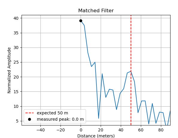
After closing the first chirp file you will see the matched filter. After zooming in on the beginning of the graph, it might look something like this. You can see that there is a slight peak at 50 m. The peak at 0 is higher because the noise traveling directly from trasmit to receiver part is louder.
It can be easier to see the peak using the “blackman” chirp window.
Running plot_samples.py
To use plot_samples.py, run python postprocessing/plot_samples.py data/<timestamp>_config.yaml. If you run this in the Raspberry Pi terminal, no plots will show up because the terminal doesn’t have the capability. It will print out a distance but at the moment I don’t think it is working.
To get the plots to show up, you need to run the files on your laptop in the WSL (this was setup in the ORCA setup step).
You will need to SCP the _config.yaml and _rx_samps.bin files to your laptop and save them in the data file in your branch or clone of the code. It can be easier to just SCP them into your laptop’s download folder and use file explorer to drag it into the proper folder.
Open the WSL terminal (you can do this in VSCode, hit CTRL + `, and use the dropdown arrow to change the terminal type to WSL)
Activate the conda environment with conda activate environment-name. You should already be in your uhd_radar folder but if not, cd into it
Run python postprocessing/plot_samples.py data/<timestamp>_config.yaml. All three graphs will show up at the same time.
Outdoor Testing
Testing with Antennas
The instructions below are a general idea on how to conduct an outdoor test. It is very open to different changes that suit your needs. Make sure to calculate the amount of power you are using so you don’t break your equipment
Testing Instructions
Wagon/trolley to carry your supplies
Large Plastic bins to use as a table or a table
2 Tripods to hold the antennas
2 Tripod-antenna adapters (allows the antennas to sit stably)
2 Vivaldi antennas
300ft Extension cable or if you have another way to get power (power bank?) but becareful of it being loud in the electromagnetic sense
Power strip (optional, but useful if you need to charge your laptop, power a monitor, power multiple Raspberry Pi’s, etc.)
300 ft Measuring tape
b205mini SDR
USB 3.0 Micro B cable (connecting SDR to Pi)
Raspberry Pi 5
Raspberry Pi 5 Power Supply (USB C)
Ethernet cable (connecting Pi to Laptop) if using hotspot SSH method you can leave this but if it’s easy to bring no harm in a backup plan
Ethernet to USB C adapter (if your laptop doesn’t have ethernet)
3 1-meter SMA male-male cables
SMA female-female adapter (or replace one of the male-male cables with a male-female cable)
30 dB inline attenuator
SMA torque wrench
Screwdriver kit
Umbrella or blanket for shade (so you can see your computer screen)
Tarp for wet grass or snow
Sunscreen
Drinking Water (if it’s summer/hot outside)
You will want an area with a clear view of a flat concrete/stone wall with no people/cars in the way, few reflections from the side, access to a power outlet within 300 ft (or however many ft long your extension cord is), and a Wi-Fi connection (or mobile hotspot) (you don’t need a Wi-Fi connection as long as the Pi is set up to be a hotspot), all while not getting in other people’s way.
The minimum distance you need to be away from the wall will depend on your bandwidth. The larger your bandwidth, the closer you can be to the wall. If you are too close for the size of your bandwidth, the noise that occurs from signals traveling directly from the transmitter to receiver will blend with the peak of power from when the signal comes back from the wall. You won’t be able to see how far the radar thinks the wall is.
A 10 MHz bandwidth needs a minimum of 100 m (about 328 ft) but 150 m is probably more preferable.
At your desired test location, place a surface (stacked plastic bins, table, etc) on the ground. You will use this surface for the Pi, SDR, etc later.
Set two tripods on the left and right of your surface. You want at least a meter of separation between the two antennas.
Attach tripod adapters to the top of the tripod.
Put the antennas on the stands. The arrows point in the direction of energy travel.
Go plug in the extension cord (or whatever power source you’re using). It may be helpful to bring something to check if the power from the outlet works (ex: a charger and a phone)
Set both the SDR and Raspberry Pi on top of the bins (or table, surface, etc)
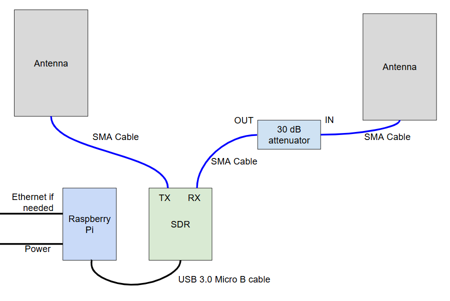
Use one of the SMA cables to connect an antenna to the TX port on the SDR.
Use the other SMA cable to connect the other antenna to the IN side of the 30 dB attenuator. You will need to use the SMA female-female adapter if you didn’t pick up a male-female SMA cable.
Use the third SMA cable to connect the OUT side of the attenuator to the RX port on the SDR. Make sure the attenuator is on the RX side to help protect the SDR’s analog to digital convertor from any other signals that might be around. Be careful of the attenuator sliding off the bin and pulling on the cables.
Make sure to use the torque wrench to tighten all of the SMA connections
Plug in the USB 3.0 Micro B cable to connect the SDR to the Pi. Plug into the blue USB slots on the Pi.
Power the Raspberry Pi with the USB C
Connect your laptop to the Raspberry Pi. Either with the ethernet cable and ethernet to USB C convertor, through SSH with Wi-Fi, or thorugh SSH with the hotspot.
You are now set up to run the code, reference the “Running the Code” section above for additional instruction
Properly eject/shutdown equipment after experiment is completed. (Running sudo shutdown)
5.1 - Runtime Overview
Overview of the code’s architecture
Conda environment setup
All of the required dependencies can be installed as a conda environment using
the environment.yaml file in the repository. More instructions can be found
in the README
file. When creating the environment, make sure your directory is in the right spot where environment.yaml can be found. You don’t need to run the code yet, we will go over that in the next step.
Startup scripts
The X series devices require some initial network configuration. For convenience,
a startup script
is provided to automate this setup. You may need to tweak this file to your setup.
Runner scripts
The basic steps required to run the radar are:
Build the C++ code
Generate a chirp file to transmit based on your configuration
Run the compiled radar code
Move the collected data to an appropriate location
The main interface for running the radar code is through run.py, a Python
script designed to automate the above process. This script is run as follows (you don’t need to run this now, we go into more detail in the next step):
python run.py config/my_radar_configuration.yaml
At the end of the data collection, data will be saved with the current date
to a location specified in the YAML config file.
Generally, three files are saved:
YYYYMMDD_hhmmss_rx_samps.bin - This is a binary file containing the raw
samples recorded the SDR. Note that this file is not interpretable unless you
also have the config file used.
YYYYMMDD_hhmmss_config.yaml - This is the YAML config file passed to run.py.
It defines all parameters of the data collection, allowing for the rx_samps.bin
file to be interpreted and processed.
YYYYMMDD_hhmmss_uhd_stdout.log - This is a text file containing the output
of running the radar code. This is helpful for debugging and also contains a log
of any errors encountered, which may be required to reconstruct the timing of
each recording.
More details on the files stored and how these can be re-processed into a Zarr
file are on the file formats page.
Note that there are also settings available to break rx_samps.bin into multiple
files as needed.
SDR interface code
For performance reasons, the code directly interfacing with the SDR is written
in C++. This code is all located in the sdr/ directory of the repository.
The main radar code is contained in main.cpp (with some SDR setup code located
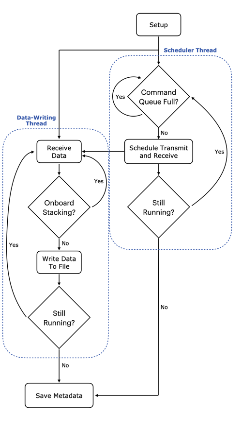
in rf_settings.cpp). The radar code runs in two threads, as shown in the
figure below.
General architecture of the ORCA code
One thread is responsible for scheduling
timed commands
that are enqueued into FIFO queues within the SDR’s FPGA.
The other thead is responsible for pulling received samples from the SDR and
writing them to a file on the host computer.
For a more complete overview, please refer to our paper:
T. O. Teisberg, A. L. Broome and D. M. Schroeder, “Open Radar Code Architecture (ORCA): A Platform for Software-Defined Coherent Chirped Radar Systems,” in IEEE Transactions on Geoscience and Remote Sensing, vol. 62, pp. 1-11, 2024, Art no. 5109411, doi: 10.1109/TGRS.2024.3446368.